
One of the most confusing issues in pro audio is the power handling for a loudspeaker. On one side, manufacturers and vendors use a variety of terms to represent these parameters. Types of speaker power parameters include:
Average Power
This parameter is a result of the testing to define power rating using one of three standards. The standards dictate the use of a bandpass (Fs to 10Fs) pink noise with 6 to 12 dB crest factor. The applying of a voltage level for two to eight hour intervals while monitoring the driver until physical damage or permanent change of driver parameters occur. This voltage value is then used to calculate this power rating by providing the square root of this voltage times the minimum or nominal impedance of the driver.
Often incorrectly referred to as “RMS” power, because of the RMS-like signal, making sense to apply RMS to it.
“Average power” is the most correct term for the power level that uses this RMS voltage for its calculation. Caution: After a review of 15 manufactures and vendors showing the incorrect labelling of this parameter, you will not see this parameter labelled as average but instead see continuous, nominal, capacity, rated, AES, AES(426B) or RMS.
Program Power
Typically this will be 3 dB greater or twice the average power derived from the standard test. Because this is random frequencies instead of pink noise, this has been defined to be the thermal power limit for the driver. Therefore this rating is the guideline for matching this driver to the correct amplifier power.
Caution: Review of 15 manufactures and vendors show the labelling of this parameter to generally be program or continuous power, but in a few cases they have been labelled music, max or peak. To be on the safe side, use the lowest rating number and double that value.
Peak Power
Typically this will be 6 dB greater, or four times the average power rating derived from the standard test. During the initial test, the 6 dB crest factor for the pink noise signal allowed for instantaneous spikes of that level and this defines the peak power level.
Caution: Review of 15 manufactures and vendors only two show this labelling of this parameter as peak. In one case, I found one manufacture showing peak power was referring to the program power. To be on the safe side, use the lowest rating number and double that value for program power and four times this lowest number shall be the peak power.
The Standards
There several standards exist that specify power test procedures. These include EIA 426A and 426B, IEC 268-5 and IEC 60268-5 along with the AES2-1984 and AES2-2012.
AES2-1984 Standard
- Bandpass pink noise (Fs to 10Fs)
- Band-limiting filtering uses 12 dB per octave.
- LF driver can use a 50-500 Hz with a 6th-order 50 Hz high-pass and 4th-order 500 Hz low-pass.
- HF driver can use 1000-10000 Hz with a 6th-order 1k Hz high-pass and 4th-order 10k Hz low-pass.
- 6 dB crest factor using a 6th-order high-pass and 4th-order low-pass Butterworth type filters
- Once the crest factor of 6 dB tends to regain its original dynamics, it will typically approaches a 12 dB crest factor.
- The duration of the test is 2 hours, after which the component should not show appreciable damage.
- Minimum impedance is used for the calculation of power.
AES2-2012 standard Superseding AES2-1984
- The AES2-1984 standard has now been superseded by AES2-2012.
- Crest factor for the pink noise signal has been increased to 12 dB (4:1)
- Nominal impedance is used for the calculation of power which results in a 20% lower rating.
- Band-limiting filtering has now been changed to 24 dB per octave (1984 version used 12 dB/octave, as seen on the graph above).
IEC268-5 (1978) standard
Superseded by IEC60268-5 (2003)
- Bandpass pink noise (Fs to 10Fs) with band-limiting filtering uses 6 dB per octave.
- 6 dB crest factor using a 6th-order high-pass and 4th-order low-pass Butterworth type filters
- Minimum impedance is used for the calculation of power.
- The terms “Rated noise power” and “power handling capacity” are used.
- Test duration is 100 hours, after which the speaker should not show appreciable damage.
EIA RS-426-A (1980) standard
Superseded by EIA RS-426-B (1998)
- This is a standard by the (USA) Electronic Industries Association.
- Also referred to as ANSI/CEA-426-B and ANSI/CTA-426-B.
- The test is not a “power handling” specification anymore but an “optimum amplifier power”.
- Includes a power compression test with a 40-10 kHz sweep sine wave played continuously in a loop,
- Bandpass pink noise (Fs to 10Fs) with 6 dB crest factor at half the rated optimum amplifier power.
- A distortion test and an 8-hour “accelerated life test” with additional test included.
- None of the tests should result in appreciable damage or change to the parameters.
- Calculation of power uses nominal impedance with 426-B instead of minimum impedance 426-A.
PerkAudio comments:
- AES standard require me to de-rate the driver because of only a 2 hour test. I operate for 4 to 8 hours at a time.
- IEC standard seems to be an overkill with a 100 hour test. Testing of one driver would be very costly.
- EIA standard is supportable with an 8 horn duration test.
Causes of speaker failure
The causes for speaker failure can only be one of two conditions:
The causes for thermal failure include:
- Running greater than two times average output power to the driver.
- Match driver program power to amplifier RMS power rating
- Excessive power outside the speaker bandpass (radio frequency, subsonic frequencies, deep bass …).
- Always use high pass filters at 35 Hz or greater depending on driver application
- Always use low pass filter at 20k Hz or less depending on driver application
- Avoid amplifier clipping which creates distortion in turn creates more unwanted heat
- Purchase amplifiers with clip circuit and monitor. Occasional flash is OK; continuous flicker unacceptable.
- I have found that if my amplifiers about 75% input volume, I do not have problems.
- Direct current at amplifier output, uncommon with today’s amplifiers but ensure DC protection feature.
- Excessive equalization on the ends of the bandpass
- Generate excessive heat with low efficiency transducers.
- Application driver minimum 3% or 97 dBSPL drivers.
- Extreme gain settings on basic LF and HF shelving which makes thermal failure more likely.
- Follow standard equalization protocols.
The causes for mechanical failure include:
- Excessive diaphragm (cone) movement.
- The speaker shows greater excursion (backward and forward movement) the lower the frequency.
- Cause voice coil to exit the gap, resulting in coil rubbing, and ending up shorting or opening windings.
- The worst case is when the coil former hits the bottom pole piece (“bottoms out”) and gets deformed.
- To prevent mechanical failure, avoid using signals below a speaker’s bandpass.
- Use an amplifier of the correct power output.
Selecting amplifier power
To match a driver or enclosure to an amplifier, use two times the continuous power of the driver or enclosure, (sometimes referred to as RMS), to the RMS rating of the amplifier with a variation of ±20%.
The amplifier’s volume controls is an input attenuator, not an output volume control. Recommended setting for the volume is at 75% (three o’clock) for best results. This will allow you to get to optimum level (0 dB) input without clipping.
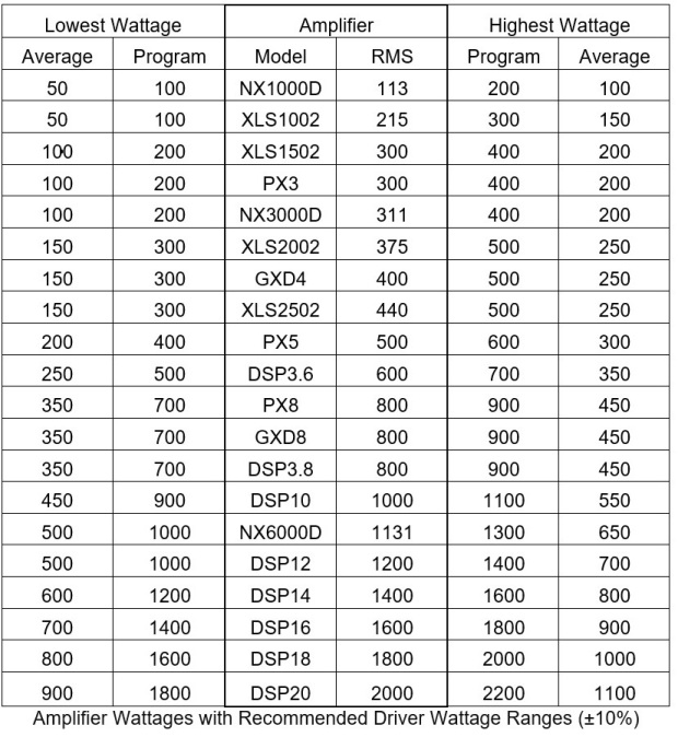
Below is a table of best priced amplifiers to show matching results. The center two columns are the amplifier model and RMS rating at 8 ohms. The left and right columns are the program and average rating for the driver or enclosure at ±10%
The above is the recommendation is for sound reinforcement applications. In other applications, such as in a guitar application, the power of the driver must be much higher than the amplifier because of the large doses of distortion in the amplifier.
